Fundamentals of Network Engineering: Foundational Concepts - Client-Server, Standards, and the OSI Model - Part 1
In today’s interconnected world, understanding network engineering fundamentals is essential for any tech professional. This guide breaks down complex networking concepts into digestible components, from client-server architecture to TCP/IP protocols.
Client-Server Architecture: The Foundation of Modern Computing
Client-server architecture divides computing workloads between powerful servers and lighter-weight clients, creating a more efficient system:
- Problem it solves: Machines are expensive, and applications are complex
- Solution: Separate applications into two components
- Workload distribution: Expensive processing happens on the server
- Interaction model: Clients call servers to perform resource-intensive tasks
- Result: Remote Procedure Call (RPC) was born
Key Benefits:
- Servers can utilize powerful hardware for intensive operations
- Clients operate effectively on commodity hardware
- Clients can still handle lightweight tasks independently
- Clients don’t require all dependencies locally
- However: We need a standardized communication model
This is where networking models come into play.
The OSI Model: Why We Need Communication Standards
The Open Systems Interconnection (OSI) model provides a conceptual framework that standardizes network communications. But why do we need such a model?
Advantages of a Standardized Communication Model:
1. Application Agnosticism
- Without standards, applications would require knowledge of every underlying network medium
- Imagine developing different versions of your app for WiFi, Ethernet, LTE, and fiber
2. Simplified Network Equipment Management
- Standards make upgrading network equipment more straightforward
- Interoperability between different vendors and technologies
3. Decoupled Innovation
- Each layer can evolve independently
- Improvements in one layer don’t require changes in others
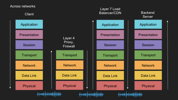
The OSI Model: 7 Layers Explained
The OSI model divides networking into seven distinct layers, each handling specific functions:
Layer 7 - Application
- Function: Interfaces directly with applications and users
- Examples: HTTP, FTP, gRPC, SMTP
- Role: Provides network services to applications
Layer 6 - Presentation
- Function: Data translation and encryption
- Examples: Encoding, serialization, encryption/decryption
- Role: Ensures data is in a usable format for the application layer
Layer 5 - Session
- Function: Establishes, manages, and terminates connections
- Examples: Connection establishment, TLS
- Role: Maintains dialogue between devices
Layer 4 - Transport
- Function: End-to-end communication and data flow control
- Examples: TCP, UDP
- Role: Ensures complete data transfer
Layer 3 - Network
- Function: Logical addressing and routing
- Examples: IP (IPv4, IPv6)
- Role: Determines how data is sent to the receiving device
Layer 2 - Data Link
- Function: Physical addressing and media access control
- Examples: Ethernet frames, MAC addresses
- Role: Transfers data between network entities
Layer 1 - Physical
- Function: Transmission of raw bit stream
- Examples: Electric signals, fiber optics, radio waves
- Role: Sends and receives data through the physical medium
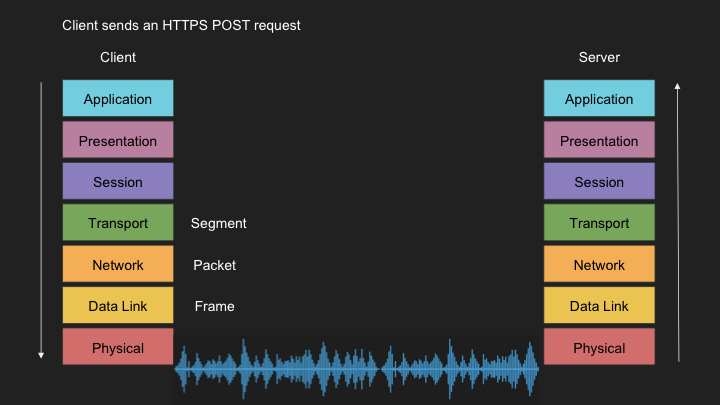
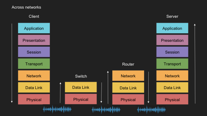
Data Flow Through the OSI Model
Sending Data: A POST Request to an HTTPS Webpage
Layer 7 - Application
- POST request with JSON data is created for an HTTPS server
Layer 6 - Presentation
- JSON data is serialized into flat byte strings
Layer 5 - Session
- Request to establish TCP connection and TLS session
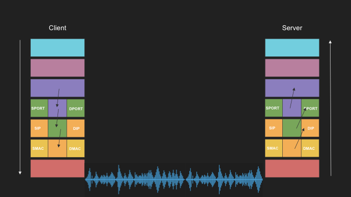
Layer 4 - Transport
- Sends SYN request targeting port 443
Layer 3 - Network
- SYN is placed in IP packet(s) with source/destination IP addresses
Layer 2 - Data Link
- Each packet is encapsulated in a frame with source/destination MAC addresses
Layer 1 - Physical
- Frames are converted into signals appropriate for the physical medium:
- Radio signals for WiFi
- Electric signals for Ethernet
- Light pulses for fiber optic connections
Receiving Data: The Reverse Journey
Layer 1 - Physical
- Physical signals (radio, electric, light) are received and converted to digital bits
Layer 2 - Data Link
- Bits are assembled into frames
Layer 3 - Network
- Frames are assembled into IP packets
Layer 4 - Transport
- IP packets are assembled into TCP segments
- Handles congestion control, flow control, and retransmission for TCP
- For SYN packets, processing may stop here as connection establishment is still in progress
Layer 5 - Session
- Connection session is identified or established
- Only reached after the three-way handshake is complete
Layer 6 - Presentation
- Byte strings are deserialized back to JSON for application consumption
Layer 7 - Application
- Application processes the JSON POST request
- Triggers appropriate handlers (like Express.js or Apache request events)
Note: The clean separation between layers isn’t always clear-cut in real-world implementations.
The TCP/IP Model: A Practical Alternative
The TCP/IP model simplifies the OSI model into four practical layers:
- Application Layer (Combines OSI Layers 5, 6, and 7)
- Application, presentation, and session functionality
- Transport Layer (OSI Layer 4)
- End-to-end communication (TCP, UDP)
- Internet Layer (OSI Layer 3)
- Routing and logical addressing (IP)
- Network Interface Layer (OSI Layer 2)
- Physical addressing and media access
Note that the physical layer isn’t officially included in the TCP/IP model.
This blog post was compiled from my notes on a Networking Fundamentals course. I hope it helps clarify these essential concepts for you!